Extortion. I'm pretty sure that was word I used when I started looking into how much it would cost to be able to use bluetooth to stream music from my phone to the head unit in my car. I have a Pioneer DEH-5850MP 50Wx4 unit, which I picked up second hand and works fine. Pioneer manufacture a bluetooth module that interfaces with their proprietary IP Bus socket on the back of the unit, and weighs in at something like $599 AUD last time I checked. My car isn't even worth that much. Additionally, the whole purpose of using bluetooth is to a) do away with cables, and b) be able to skip tracks without having to touch my phone. Which the Pioneer unit still wouldn't offer. So I started thinking about what I could hack together for the purpose.
Nokia BH-503 headphones.
The Nokia BH-503. These are the bluetooth headphones I use day to day for streaming music to my brain. Rechargeable, lightweight, and feature audio controls on the right side earpiece. I came up with the idea of using the PCB as the basis of a system that would suit my needs. I had a broken BH-501 (predecessor model, volume and call answer/end functionality only), so I drew up a circuit in the most bad arse design program going, MS Paint, to see how it would come together. The picture does have an obvious open circuit, which in hindsight needs a resistor, followed by connection to +12v DC to bring the supply voltage for the LEDs in the push buttons to 3.5-4.0v. More on illuminated push buttons later.
BH-501 concept circuit diagram.
So that was cool. Guess the headset needed to be cracked open, to see how damn small the Fins had made it. Some of these pictures will be the BH-501, but towards the end they will all be the BH-503.
BH-501 PCB, showing connections and former Nokia ingenuity.
There are three PCB mount push buttons, two pairs of speaker wires, a pair of wires for the battery, and the microphone. The processor is beneath the copper shield. Because I guess he's a douche. Anyway, knowing minimal about TRS audio configurations, I had to work out how to attach a female 3.5mm stereo TRS socket to the PCB using the four speaker pads. So that's four wires off the PCB going into three on the socket. The assumption was made that both channels can get away with a shared earth, whilst the positive sides go to their respective pins on the socket to keep the channels separated. Funnily enough, this actually worked. I did this by putting a tiny U-shaped piece of wire between the two earth pads, then attaching the TRS socket earth wire to one of them.
My old Nokia N900, which I literally sold today, A2DPing Radiohead to my
PC speakers via the connected TRS socket.
The next step was power. The BH-501/3 runs on 3.7v DC, as is cleverly stated on the front of the 260mAh battery that powers it. Herp derp. So I figured running 12v DC from my car battery through it may cause some slight problems. In comes the LM317T, who sits down and says "I got this guys". The LM317T is a voltage regulator that can be used for reducing input voltage to an appropriate level. I'm sure it does other things too. Using the datasheet, LM317T calculator (http://www.reuk.co.uk/LM317-Voltage-Calculator.htm) and my multimeter, I worked out what resistors to run it with to achieve the right voltage. Initially I had R1 set at 240Ω, and R2 at 470Ω, which resulted in 3.67v; unfortunately this caused some noise in the end product (crackles). Talking with an audio enthusiast over on TMO (talk.maemo.org), it was suggested to bump up the supply voltage slightly, as bluetooth audio units tend to play up under limited power conditions. With R1 at 220Ω, and R2 at 470Ω still, we were running nicely at 3.9v DC. It must've been quite funny for my neighbors to see me come outside with this bundle of wires that probably looked like a bomb, some headphones and a phone, hook them up to my car battery for five minutes, then go back in the house. Aaaand repeat. Many times over.
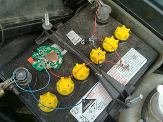
BH-501 running off 12v DC by use of a LM317T. And a lot of swearing.
So fast forward a bit, and skipping the plethora of problems I encountered (mostly inability to sensibly place components on a protoboard), I was ready to mount the BH-503 board in a project box, with a cable bundle coming out of a hole in the side, with all the necessary plugs. I didn't take a picture of this, but after using the finished project for a few weeks I started to smell that plastic-getting-slightly-too-hot-but-not-burning-yet smell. The LM317T was converting the excess voltage to heat, which I somehow calculated using some physics maths on found on the internet, and then measured. Temperature was reaching around 75°C, so I built a very small power circuit on a piece of protoboard, allowing the LM317T to be free standing (instead of laying down under a layer of tape), and then made a heat sink out of a bit of an old computer case. I also drilled three 6mm hole in the lid directly above the heat sink, and it's been fine ever since.

How it initially went in the car, before the overheating issue.
Close up of the component layout inside the project box (pre-overheat).
The last thing I needed to do was create a bank of buttons to control the BH-503, and the music I'm listening to. I only needed seek/skip backwards, play/pause, and seek/skip forwards, so I bought three back lit PCB mount push button switches (http://www.jaycar.com.au/productView.asp?ID=SP0614). Because the amps available to the unit is whatever my alternator puts out (probably minimum 70A), I can run the LEDs in the push button switches on the same power circuit. Well, there's probably a better way to do it, but that was my logic and it works well. Using an LED array calculator (http://led.linear1.org/led.wiz), I worked out I only needed one 10Ω resistor to power the bank. This was made as small as possible, to mount in the dash fascia between the bottom of my head unit and the pocket where I put my phone while driving.
The bank of LED back lit push button switches mounted in the removable dash fascia.
Front view of the bank.
And with that, came time to mount it in the car. The car in question is a 1995 Mitsubishi TS Magna sedan (executive), sporting the "burly" combination of a V6 and manual transmission. Because it's basically a poverty pack, I have a lot of room in front of the gear stick and directly below the head unit. Perfect for fitting stuff in - if I was doing a carputer I'd be set. The box is now mounted to the dash support frame with the most versatile and useful building material known to man, the zip tie, with the plugs for power, lights and button bank going off in their respective directions. The head unit is connected to this fire hazard by an IP bus to 3.5mm TRS male cable, off eBay for a few bucks. Love it how all these weird cable combinations all come out of Hong Kong. They must have some insane backyard hacking going on over there.
And we're left with this.
The finished product, with horrible reflective dome self-tappers.
This has all been running wonderfully for about six months now, firstly with my N900, and now an SGS2. I should mention the multifunction button that turns the unit on and off and makes new pairings, is routed to a blank factory button on my dash just above the head unit. Unfortunately, the head unit has to be turned up to 50/60 (volume) to get loud sound out of it, so I'm looking into building a small inline amplifier to boost the signal before it reaches the head unit. Enjoy, modify to your own needs.
-Tim
Edit: found a completed picture!
Completed unit after the overheating incident. Notice the power
circuit with heat sink.


